des-inv
CNC Mill 1 — Part B Drawing CNC Mill 1 — Part B Drawing
Part drawing for CNC Mill 1 upgrade, Part B. Material: HDPE 4” × 6”. TEAMLab standard tolerances.
Part Drawing
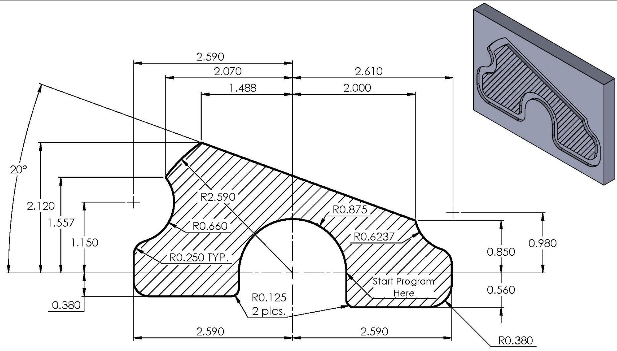
Dimensions
| Feature | Value |
|---|---|
| Stock | HDPE 4” × 6” |
| Tool | .250 dia. 2-flute end mill |
| Depth | 0.125” |
| Scale | 1:1 |
| Sheet | 1 of 1 |
Key geometry (all dimensions in inches):
- Overall profile width: 2.590”
- Overall profile height: 2.590”
- Entry radius R2.590 (large outer arc)
- Internal radii: R0.660, R0.875, R0.6237
- Corner radii R0.250 TYP (typical, 2 places)
- Small fillet R0.125
- Angled face: 20°
- Start program at indicated point (0.850, 0.980 from origin)
- Slot depth R0.380
Notes:
- Use .250 dia. 2-flute end mill
- Machine to a depth of .125”
- Center profile in plastic stock
Title Block
| Field | Value |
|---|---|
| Title | CNC 1 Part B |
| Material | HDPE 4” × 6” |
| Scale | 1:1 |
| Tolerances | Fractional ±.025 · 2-place decimal ±.01 · 3-place decimal ±.005 · Angular ±.1° |
| Organization | TEAMLab |
See Also
- cnc-1 — lab instructions for making this part
- cnc-mill-1a — Part A companion drawing